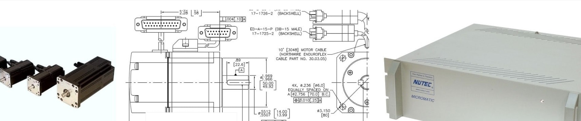
An integrated 1-, 2-, 4-, or 6-axis motion controller and amplifier system with 5 amps continuous and 10 amp peak current capability. MICROMATIC-9 a convenient and compact package, that can be programmed for virtually any type of motion control application, including XY Stages and Tables, Pick and Place applications, CNCs, PLC programming., and more.
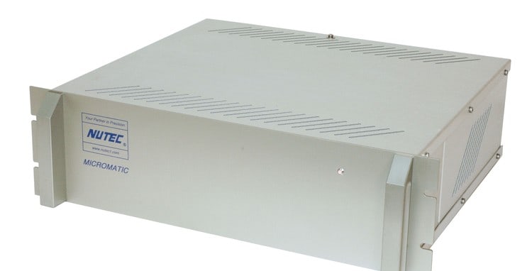
MICROMATIC-9 axis motion controller is available as a multi-axis integrated digital servo controller and drive amplifier. This is completely integrated control system featuring USB and Ethernet interfaces to a user supplied, host PC or other system controller. Micromatic-9 is a true stand-alone motion controller. The device includes its own motion control microprocessor and flash storage enabling motion system operation independent of a host computer. This device includes a home routine and all servo parameters. Micromatic-9 delivered in a package intended for panel mount. Control electronics includes the following items; all interconnect cables, servo tune, testing and burn-in.
Position Synchronized I/O
The Micromatic-9 addresses Position Synchronized I/O for Precision Laser Shuttering and other applications. Using the standard I/O, the Micromatic-9 has high-speed position compare outputs allowing for output control triggered by actual position. The circuit will fire within 100 nsec of reaching the desired position. The position compare output port is enabled by fast CMOS drive technology. Position Compare is programmed deterministically, or non-deterministically in a background process PLC. GUI programmers can read/write from shared RAM for ever changing path and control requirements. No additional hardware is required.
Analog Input and Programmable PWM Output
The Micromatic-9 offers an Analog I/O option to add two 16-bit ±10V A/D converters as well as one differential 12-bit filtered PWM analog ±10V output. Use the A/D for joystick interface, for analog data sampling or data logging. Use the PWM output for PRF triggered control or alike.
G-CODE
Program using familiar RS274D or G-Code, commonly used for NC and CNC machine tools. G-Code support can also be expanded to include compound routines or other machine specific codes. For a head start, ask about our available G-Code Interpreter workspace.
nuFace™ for PC based CNC Control
For turn-key NC software, ask about our Windows-based customizable GUI nuFace™ for PC based CNC control. nuFace™ is NUTEC’s own PC based RS274 (G-Code) end user application developed from the ground-up for any type of application which requires convenient control of a dedicated or generic multi-axis machine. A short learning curve, clear graphics, flexibility for customization and ready availability are features of this off-the-shelf GUI.
Communications Library
Optional Software Support COM Library interface is available for C++, C#, and VB development environments. Interface provided Ansi C type functions to Matlab or LabVIEW.
LabVIEW Panel
Also optionally available is our LabVIEW Panel interface including over 250 Virtual Instruments (Vis). Motion that triggers acquisitions and responds to data gathered by SCXI, VXI, and industrial automation networks such as DeviceNet and Field Bus are now possible using LabVIEW’s popular and powerful graphical programming environment.
GUI development for NON programmers
For inexperienced programmers, ask about our intuitive HMI Pro which allows users to quickly build their customized front-end in hours or days instead of weeks and months without the difficulty and learning curve of programming languages or other software methods. No special software knowledge or expertise required.
Other Features
| Main Input Power | 5/10A | 10/20A | 5/10A | 6/16A | 5/10A | 8/16A |
| Nominal Input Voltage (VAC) | 110 | |||||
| Rated Input Voltage (VAC) | 97-265 | |||||
| Rated Continuous Input Current (A ACRMS) | 3.3 | 6.6 | 13 | 21 | 13 | 21 |
| Frequency (Hz) | 50/60 | |||||
| Phase Requirements | 1 φ or 3 φ | |||||
| Main Bus Capacities (µf) | 3380 | |||||
| Output Power | ||||||
| Rated Output Voltage (V) | 138 | |||||
| Rated Cont. Output Current per Axis | 5 | 10 | 5 | 8 | 5 | 8 |
| Peak Output Current (A) for 2 seconds | 10 | 10 | 10 | 16 | 10 | 16 |
| Rated Output Power per Axis (Watts) | 1195 | 1195 | 1247 | 1995 | 1247 | 1995 |
| Bus Protection | ||||||
| Nominal DC Bus (VDC) | 340 | |||||
| Over-voltage Trip Level (VDC) | 420 | |||||
| Under-voltage Lockout Level (VDC) | 10 | |||||
| Shunt Regulator Ratings | ||||||
| Turn -On Voltage (VDC) | 392 | |||||
| Turn-Off Voltage (VDC) | 372 | |||||
| Control Logic Power | ||||||
| Input Voltage (VDC) | 20-27 | |||||
| Input Current (A) | 2 | 2 | 3 | |||
| Transistor Control | ||||||
| Recommended PWM Frequency (kHZ) @rated current | 12 | |||||
| Minimum Dead time (μs) | 1 | |||||
| Charge Pump Time (% of PWM period) | 5 | |||||