Single Axis Servo, or SAS, is a compact, AC powered servo drive for position, velocity and torque control of AC Brushless and DC Brush Motors. It operates on a distributed control network, as a stand-alone indexing drive, or with external motion controllers.
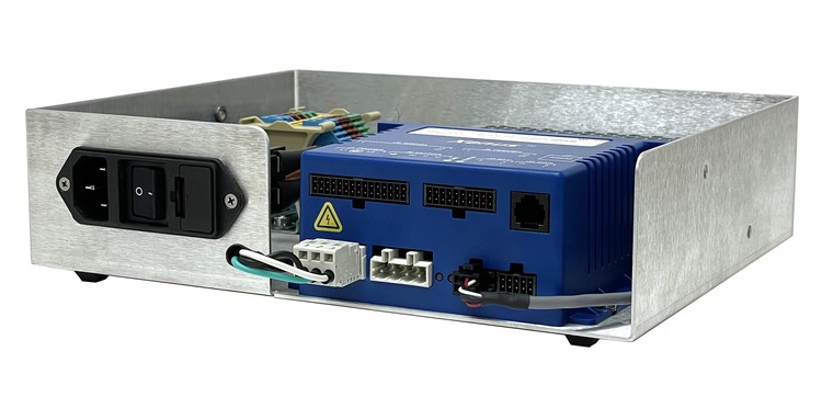
SAS is packaged with an intelligent control to offer a low cost, high performance single axis motor drive solution. Operate as an indexer, or program for point-to-point and/or Position-Velocity-Time (PVT) Motion. PVT mode gives users direct control over the trajectory profile as you specify the end position or distance, the end velocity, and the piece time
SAS can be operated in Indexing mode to simplify operation with PLCs. DeviceNet capability enables multiple drives to be controlled from Allen-Bradley PLCs. CAN bus operation supports Profile Position, Profile Velocity Profile Torque, Interpolated Position , and Homing. Multiple SAS drives can operate linked via the CAN so that they execute motion profiles together. Up to 127 drives can operate on a single CAN bus.
SAS finds uses in single axis point-to-point applications where high torque / load positioning demand the use of closed loop servo motors
SAS is a good choice where single axis controlled Point-to-Point movement is required. However, Up to 127 drives can operate on a single CAN bus.
Software Support
LabVIEW
The most common communication method used by the National Instrument (or LabVIEW) customer is the RS-232 ASCII protocol. LabVIEW includes general use tools in their software to control both CANopen and RS232 ASCII devices, such as our SAS series control.
Main Input Power |
1/2A |
3/6A |
5/10A |
|
Rated Input Voltage (VAC) |
85-264 |
||
|
Frequency (Hz) |
50/60 |
||
|
Phase Requirements |
3 φ |
||
|
Peat time seconds |
1 |
||
Output Power |
|
||
|
Rated Cont. Output Current per Axis |
0.7 |
2.1 |
3.5 |
|
Peak Output Current (A) for 2 seconds |
1.4 |
4.2 |
7.1 |
Regeneration |
|
||
|
Type |
Internal MOSFET dissipater |
||
|
Power Dissipation Peak (Continuous) (Watts) |
80 (40) Watts |
||
Digital Control |
|
||
|
Digital Control Loops |
Current, velocity, position. 100% digital loop control Dual loop position control using secondary encoder input |
||
|
Sampling rate (time) |
Current loop: 15 kHz (66.7 us) Velocity, position loops: 3 kHz (333 us) |
||
|
Commutation |
Sinusoidal field-oriented control or trapezoidal for brushless motors |
||
|
Bandwidth |
Current loop: 2.5 kHz typical, bandwidth will vary with tuning & load inductance |
||
|
HV Compensation |
Changes in bus voltage do not affect bandwidth |
||
|
Minimum load inductance |
200 μH line-line |
||
Digital Inputs |
|||
|
Number |
14: 12 programmable, 1 input dedicated to drive Enable function, 1 for motor temp switch |
||
|
Type |
8 General-purpose (GP), 3 high-speed single-ended (HS), 2 high-speed differential (HSD), 1 motemp (GP) |
||
|
GP, HS |
74HC14 Schmitt trigger operating from 5.0 Vdc with RC filter on input, 10 kΩ to +5 Vdc or ground (programmable), Vin-LO < 1.35 Vdc, Vin-HI >3.65 Vdc +10 Vdc max for HS inputs, +24 Vdc max for GP inputs 1.5 MHz ma pulse freqfor HS inputs when driven by active (not open-collector) sources |
||
|
HSD |
Differential, 121 Ω line-line, 100 ns RC filters to RS-422/RS-485 line rcvrs, +10 Vdc max 5 MHz maximum pulse frequency when driven by differential line-drivers |
||
|
Pull-up, pull-down control |
GP & HS inputs are divided into three groups with selectable connection of input pull-up/down resistor to +5 Vdc or ground for each group: [IN1,2,3,4], [IN5,6,7,8], [IN9,10,11] |
||
Digital Outputs |
|
||
|
Number |
14: 12 programmable, 1 input dedicated to drive Enable function, 1 for motor temperature switch |
||
|
[OUT1], [OUT2], [OUT3] |
Current-sinking MOSFET with 1 kΩ pull-up to +5 Vdc through diode |
||
|
Ratings |
250 mAdc max, +30 Vdc max External flyback diode required if driving inductive loads |
||
|
Brake [OUT4] |
Opto-isolated, current-sinking with flyback diode to +24 Vdc, 1 Adc max |
||
Power |
|
||
|
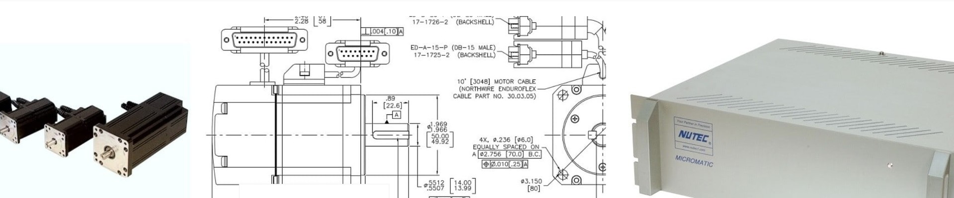
Motor Connections |
U-V-W phases for brushless, U-V for brush motors |
||
|
Commutation |
Digital Halls, or sin/cos feedback from ServoTube motors |
||
|
Feedback |
Digital quadrature A/B/(X) encoders; differential inputs (Standard) Analog sin/cos enc, 1 Vpeak-peak, differential inp with 121W terminating resistor (option) Resolver, brushless, single-speed, 1:1 to 2:1 programmable transformation ratio (option) |
||
|
Brake |
Digital output, isolated, 1 Adc, +30 Vdc max, programmable, with flyback diode to +24 Vdc |
||
|
Overtemp sensor |
Digital input, non-isolated, 4.99 kΩ pull-up to +5 Vdc, programmable |
||
LED Indicators |
|
||
|
Drive Status |
Bicolor LED, drive status indicated by color, and blinking or non-blinking condition |
||
|
CAN Status |
Bicolor LED, status of CAN bus indicated by color and blink codes to CAN Indicator Specification 303-3 |
||
Mechanical |
|
||
|
Size |
126 x 89 x 53 [5.0 x 3.5 x 2.1] mm [in] |
||
|
Weight |
0.67 lb (0.30 kg) |
||