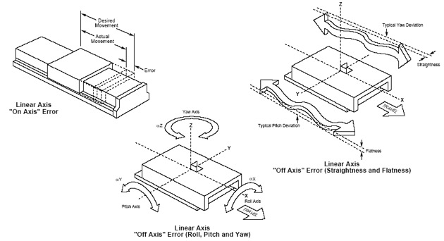
Total Sum of Errors in Multi-axis Systems Is Always Greater Than the Addition of Errors in Each Axis.
“Point of Interest” Is Never on One Plane Only.
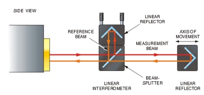
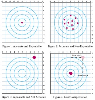
Maximum Observed Difference in Distance Between Move Instruction and Actual Position - Measured by the Laser Interferometer.
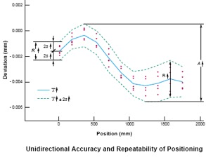
Range of Difference in Position Observed When Returning to a Targeted Position.
With All External Conditions Equal, to What Degree Does the Positioner Provide the Same Result for a Fixed Input. a.k.a. Precision
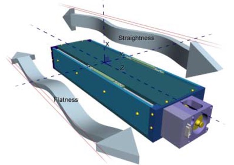
Bandwidth of Transversal Movement Observed Deviating From Ideal Linear Trajectory.
Perfect Stage Would Have 0.0 μm (nm) Flatness/Straightness Error.
The Transverse Position Deviations Along an Axis, Which Fall Between Two Imaginary Parallel Planes That Run Along This Axis.
Measures the Ability of the Moving Component to Change Orientation Around The 3 Cartesian Coordinate Axes.
Angular Errors Reported in Arc-Second , milli-radians or micro-radians.
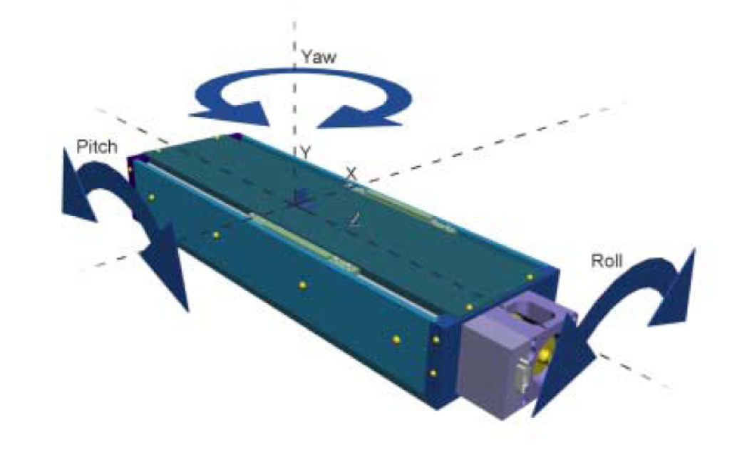
Because We Are Positioning Extended Bodies YPR Errors Are a Component of Observed Straightness and Flatness Performance.
YPR Also Manifests as “Apparent Error” in Orthogonality.
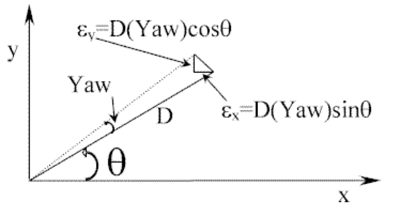
Cartesian Systems (XYZ), Orthogonality Describes “Squareness” Between Architectural Axes Is a Major Component in “Point-of-interest” Positioning.
Reported by Angular Deviation, From Ideal in Degrees, Micro-radians or Arc Seconds.
| Arc seconds | Degrees ø | Linear Deviation (µm) = L * Sin ø | |||
|---|---|---|---|---|---|
| 100mm | 150mm | 200mm | 300mm | ||
| 5 | 0.001389 | 2.4 | 3.6 | 4.8 | 7.3 |
| 10 | 0.002777 | 4.8 | 7.2 | 9.6 | 14.6 |
| 15 | 0.004167 | 7.2 | 10.9 | 14.5 | 21.8 |
| 20 | 0.005556 | 9.7 | 14.5 | 19.4 | 29.1 |
| 25 | 0.006944 | 12.1 | 18.2 | 24.2 | 36.4 |
The Measure of Deformation (Elastic) in the Translator under the Effect of Gravity, Payload or Inertia.
All tests must be performed in a temperature controlled environment (20°C, 68°F). This provides a standard reference temperature. Changing the environmental temperature causes thermal expansion and contraction, which can cause significant positioning errors (approximately ± 11.7 microns per meter per degree C).
All tests must include a full warm up cycle that simulates actual operating conditions prior to testing. Some manufacturers purposely omit a warm up cycle to overstate the accuracy of their systems because omitting a warm up cycle prevents the thermal expansion of the drive train caused by frictional heating.
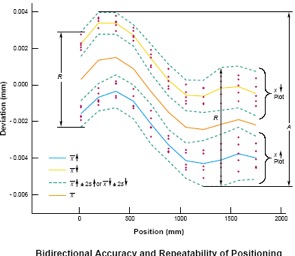
All tests clearly specify unidirectional (approaching target points from one direction only) and bi-directional approaching target points from both directions) positioning performance with statistical error bands.
Linear axes require at least 5 target points per meter. It should be measured at random intervals to avoid masking periodic errors (e.g. a metric drive system has target points spaced in inches).
Rotary axes require at least 3 target points per 90 degrees.
Each test requires at least 5 trials per target point per direction of approach. Utilizing multiple trials per target point allows statistical error bands to be calculated. According to the current ISO 230-2 standard, the typical error band is ± 2 times the statistical estimator (standard deviation).