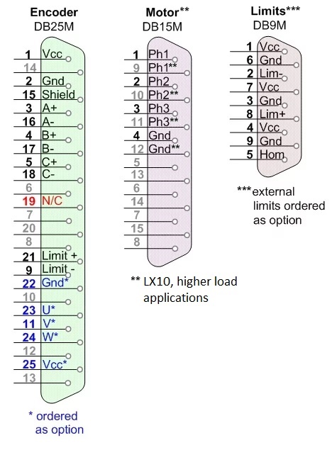
The Encoder, Motor and Limit interface connectors are industry standard DB type connectors. Stage assembly interface gender is male, enabling pin-to-pin connection to our MICROMATIC-9 where female mates are found.
|
DB25 |
ENCODER |
|
1 |
5VDC, Power Supply |
|
2 |
Ground |
|
15 |
Shield |
|
3 |
A + |
|
16 |
A - |
|
4 |
B + |
|
17 |
B - |
|
5 |
C +, Index Reference |
|
18 |
C - , Index Reference |
|
8 |
No Connect |
|
19 |
No Connect |
|
21 |
Limit + |
|
9 |
Limit – |
|
22 |
Ground * / No Connect |
|
23 |
HED U * / No Connect |
|
11 |
HED V * / No Connect |
|
24 |
HED W * / No Connect |
|
25 |
5VDC * / No Connect |
|
* |
Ordered as option Otherwise NO CONNECT |
|
DB15 |
MOTOR |
|
1 |
Phase 1 / R |
|
2 |
Phase 2 / S |
|
3 |
Phase 3 / T |
|
4 |
Motor Ground |
|
9 |
Phase 1 / R ** |
|
10 |
Phase 2 / S ** |
|
11 |
Phase 3 / T ** |
|
12 |
Motor Ground ** |
| ** | LX10, high load applications |
|
DB9 |
Limits |
|
1 |
Power, 5 to 24 VDC |
|
6 |
Ground |
|
2 |
Limit – (CW) |
|
7 |
Power, 5 to 24 VDC |
|
3 |
Ground |
|
8 |
Home / Index |
|
4 |
Power, 5 to 24 VDC |
|
9 |
Ground |
|
5 |
Limit + (CW) |
Linear/Rotary Scale Position, Index and Limits
Standard with LINEAX, Theta4 & TMax. Order as option for Flexdrive.
Encoders are differential quadrature position and index signals, RS422 compliant, and follow the EIA-422/485 bus interface specification. RS422 compliance dictates that the composite differential signal logic must fall within the 2 to 6 volt voltage band.
These limits are HIGH True, "Normally Closed". In this configuration any break of wire will stop motion, an added security to ensure signal integrity.
All above references to INDEX call out the signal for a specific axis "zero" location mark. The community uses any of the following names: C, HOME, INDEX, REFERENCE, and Z.
HEDs for commutation can be ordered as option.
These pins should otherwise be “No Connect” or not used.
Pin 19 is used for test purposes and must not be wired.
Three phase brushless servo motors include phases 1, 2 & 3, sometimes called R,S & T.
Ground should be connected to amplifier or its chassis ground.
BSM series motors are recommended for use on Flexdrive and RT series rotary stages.
External Adjustable
Order as option with Flexdrive & RT series rotary stages.
Standard configuration are limits wired HIGH True and current is sourced from the control. The intent is that the limit switch itself provides a ground path when travel is legal. If the axis travels into limit, the signal path is broken and limit is “pulled" high at the control and motion is stopped. In this configuration any break of wire will stop motion, an added security to ensure signal integrity. This is "Normally Closed" behavior.
Up to three External limits are ordered as option. External limits can be powered by a 5 up to 24 volts power supply voltage. Default configuration operates as output Light –ON. Contact factory for Dark-ON configuration at time of order.
Switch is NPN Type
50 ma Max Current Sink
Normally Closed Behavior
For wet process applications water resistant multipole, push-pull latching connectors can be ordered. They include an inner sleeve and two seals to prevent penetration of solids or liquids into the housing formed by the fixed socket.
|
EEG 2K.4 |
MOTOR |
|
1 |
Phase 1 / R |
|
2 |
Phase 2 / S |
|
3 |
Phase 3 / T |
|
4 |
Motor Ground |
|
EEG 12K.12 |
ENCODER |
|
1 |
5 VDC, Power Supply |
|
2 |
Ground |
|
3 |
A + |
|
4 |
A - |
|
5 |
B + |
|
6 |
B - |
|
7 |
C +, Index / Reference + |
|
8 |
C -, Index / Reference - |
|
9 |
Limit - |
|
10 |
Limit + |
|
11 |
Test |
|
12 |
Shield |
The Micromatic-9 addresses Position Synchronized I/O for Precision Laser Shuttering and other applications. Using the standard I/O, the Micromatic-9 has high-speed position compare outputs allowing for output control triggered by actual position. The circuit will fire within 100 nsec of reaching the desired position. The position compare output port is enabled by fast CMOS drive technology. Position Compare is programmed deterministically, or non-deterministically in a background process PLC. GUI programmers can read/write from shared RAM for ever changing path and control requirements. No additional hardware is required.
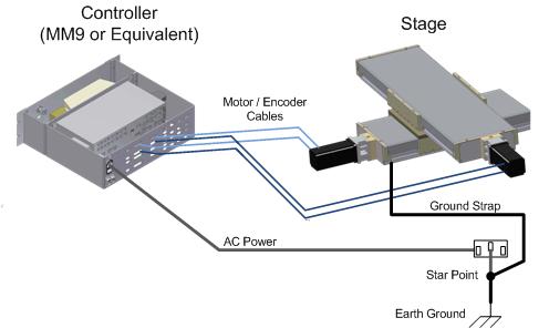
The stage or positioner may itself conduct some signal noise. Attach a ground strap to the stage or position using the provided, un-painted, un-anodized, tapped M4 hole. The ground strap will provide a drain path to earth ground.
In general, it is good practice to shield all wires carrying low level signals. This is especially important if the signal level wires are run near power level wiring such as motor wires or relay wires. When shielding wires, connect only one end of the shield, preferably the source end. Connecting both ends of a shield will result in ground loops. It is recommended that the unconnected end of the shield be insulated to prevent accidental connection.